Creating your own templates
So, how to create your own geometries? Read here to learn, or at least get started.
Other reading
Please also check
Model hierarchy
Before anything else, let’s rehash how analysis with EMDtool works. Like we saw in the EMDtool briefly page, we obtain results by first solving a problem object.
The problem, just before has eaten is associated with a Model. 95 % of the time, it is an RFmodel, containing as components a stator and a rotor. The model has a few additional responsibilities, like
-
Returning an airgap matrix for modelling rotation. You may have to overwrite this method to study e.g. magnetic gears or other systems where you have two or more components rotating at different speeds.
-
Returning some properties for the components. For example, the stator and rotor typically are at different temperatures, and see a different frequency in harmonic analysis.
Anyways, this now brings us to the components, for example the stator. Each component is a subclass of the GeoBase class, typically called a template. To create your own custom geometries, templates are what you have to work with.
Geometry components
Geometry components - subclasses of the GeoBase class - each describe one “independent” component of the problem geometry - think a stator and a rotor.
Each component contains all the information required to describe it (in analysis-terms at least), in the corresponding properties:
-
.mesh: a mesh object, containing the finite element mesh elements and nodes -
.domains: Domains of the component, each corresponding to an interesting part of the component, like for example the stator core. Each Domain then contains at least:-
The Material it is made of.
-
The elements that belong to it.
-
-
.materials: all Materials that are present in the component. -
.circuits: all Circuits in the component, if any.
Finally, what turns a mere component into a template is the fact that it is parametric. This means that each template class implements the .create_geometry method. This method takes as an input a structure of dimensions, and uses the information to create the Domains, Materials, Circuits, and enough information to allow automatic mesh generation with the .mesh_geometry method. More of this shortly.
Minimal symmetry regions
Before diving deeper into geometry templates, let’s repeat one important detail: EMDtool is very much tailored towards modelling repetitive geometries.
After all, most electrical machines are like that. Each rotor pole is often identical to the others, as is each stator slot. Please note that we are only speaking about the geometry here - of course each slot will typically host different coil sides, and each pole will be magnetized in a different direction. Yet, the geometry - the shapes of everything - will be just repeated.
The great-parent component classes - often a RadialGeometry (in turn a subclass of GeoBase) are built with precisely this in mind. Indeed, it is assumed that the .create_geometry method of any subclass only creates the geometry for one slot or pole pitch. The boring parts, such as
-
meshing the slot or pole pitch
-
replicating and rotating the mesh enough times to cover the required model sector
-
gluing the repeated mesh components to each other
-
assigning the correct materials and boundary conditions to the replicated parts
-
assigning the replicated parts to the correct circuits
-
updating permanent magnet or material orientation
are then taken care by the parent classes.
Creating a geometry template
Like implied above, you can create geometry template class by subclassing the GeoBase class, and then implementing the .create_geometry method.
Note: in practice, you will in fact be subclassing another subclass such as StatorBase, SlottedRotorBase, or SynRotorBase. This is because many of the finer analysis features require some other methods from the templates. An example is the .d_axis_angle for rotor templates, to allow automatic dq-transformations.
Most likely, you will implement the .create_geometry method in its own separate file. Inside the file, you will generally do the following steps:
-
Create the
Materials used in the model, and add them to the component. -
Create the
Domains used and add them to the component. -
Create the
Circuits used, and add them to the component.
Now, let’s take a brief look at each of these steps.
Creating Materials
Materials are objects, and subclasses of the MaterialBase class. Most importantly, they contain the functionality required for modelling the (generally non-linear) B-H relationship of the material in question.
The majority of the time, your materials will be of the simple anisotropic, non-hysteretic Material class, and created using one of the following methods:
-
Using the
Material.create(0)method to use one of the earlyEMDtoolbuilt-in materials. In the example before, the index 0 would be for air, folks -
Using the
PMlibrary.createorSteelLibrary.createmethods, to gain access to more, newer, and more regularly-updated materials. -
Use your own materials, most often wrapped inside a function calling the
Material.from_specsmethod.
After creation, the material objects are added to your component with this.add_material( material_object ). Here this of course refers to your template object, like this in Java or self in Python). For some reason, the Matlab documentation uses obj instead.
Creating Domains
Domains are also objects, each consisting of a single material (at least for the foreseeable future), and representing one interesting part of the geometry. For instance, one bar of an induction motor would normally by a Domain, as would the part of the stator core within one slot pitch.
- Domains must be uniquely named, with names suitable to used as fields of Matlab structures (no spaces!)
Domains themselves are very easy to define. However, for them to actually mean anything, you will have to add one or more Surfaces to each of them, to tell EMDtool something about the actual geometry. We will take a closer look on this later.
For now, the code snippet below demonstrates the usage of Domains in a simple form.
core_domain = Domain('Rotor_core', core_material);
core_domain.add_surface(core_surface);
this.add_domain(core_domain);
Creating Circuits
Although optional, Circuits do feature as a part of most geometry templates. After all, motors typically have windings where currents should flow, and other conductive bodies where they should not but still do (eddy currents).
An example tells more than a thousand words, so here is one:
core_circuit = SheetCircuit('Rotor_core');
core_conductor = SolidConductor(core_domain);
core_circuit.add_conductor(core_conductor);
this.add_circuit(core_circuit);
In this example, we are presumably dealing with a high-speed induction motor with a solid core. To model the eddy-currents induced into the core, we have to create a CircuitBase object for it.
Specifically, we will create a SheetCircuit object. A sheet circuit is a special kind of circuit, reserved for solid bodies that span the entire circumference of a motor. Think a cylindrical copper shell (a sheet) used as an eddy current shield, a solid shaft, a solid frame, or indeed a solid core.
Note: Were we modelling the entire cross section of the machine, there would be nothing special about a sheet circuit. However, the assumption in EMDtool is that we are only modelling one symmetry sector. Say we have a conducting body in the symmetry sector, and by extension a similar body in all the other (non-modelled) sectors. In reality, the sector-bodies may form a single continuous body (like a shaft or our rotor core in the example), or they may be separate from each other (like a PM segment inside an IPM rotor). The former case would call for a SheetCircuit, whereas for the latter a BlockCircuit or perhaps an ExtrudedBlockCircuit would be more appropriate.
Back to the example: after creating the circuit, we create a SolidConductor object to wrap the Core Domain created earlier. Then, this conductor is added to the circuit, and the circuit is added to the geometry template itself.
Creating Surfaces
The trickiest part of a template creation is usually creating the actual geometry: Points, Curves, and Surfaces. This step is best learned by checking the existing templates and the familiarization exercises. But, the overall process is as follows:
-
Creating a set of unique Points
- Newest versions of EMDtool try to check for dublicate point definitions (two separate
Pointobjects at the same coordinates) and update things accordingly. This seems to work alright and can be handy on many occasions.
- Newest versions of EMDtool try to check for dublicate point definitions (two separate
-
Connecting them with Curves (Lines and Arcs) to create surfaces. Please note that intersections and T-junctions are not allowed, nor checked automatically.
-
- Not each Curve needs to be manually created. Using
some_surface.add_curve(geo.line, Pstart, Pend, <curve_name>)orsome_surface.add_curve(geo.arc, Pstart, Pcenter, Pend, <curve_name>)creates a newCurveif not yet created. You can later fetch the created curve withLine.from_points(Pstart, Pend)orArc.from_points(Pstart, Pcenter, Pend)if you want to e.g. rename it.
- Not each Curve needs to be manually created. Using
-
-
Handling concentric surfaces as holes (inner as a hole to the outer one) with
outer_surface.add_hole(inner_surface) -
Adding the
SurfacestoDomains -
Setting periodic curves by calling
geo.set_periodic -
Setting dirichlet and airgap boundaries by naming the associated curves as ‘n_dir’ and ‘n_ag’ respectively
-
Calling
geobase_subclass_name.check_healthchecks for intersecting lines and overlapping surfaces. Not 100% tested but seems to work. -
Verifying that the mesh looks good with
stator.mesh.triplot([]): Seeing that there are no doubly-meshed areas (which happens when you forget to add holes) and that there are no non-matching nodes on the boundaries.
Case Example: Solid Rotor for a High-Speed Induction Motor
Next, let’s take a look at a very simple yet complete-ish template example. The template in question is for a very simple high-speed induction motor rotor: no slits, no coats, no shaft.
The template is located inside a folder called @SimpleSolidRotor, with the @-sign telling Matlab that a folder defines a class.
Inside the folder, the first file is the main class definition file SimpleSolidRotor.m. Its entire contents are listed below:
classdef SimpleSolidRotor < SynRotorBase
    methods
        create_geometry(this)
    end
end
So, the class inherits the SynRotorBase class. Even though not synchronous, inheriting this class saves us some trouble of implementing some other functionality needed (see the RadialGeometry class for a list).
Furthermore, the class file tells Matlab that the main geometry creation function create_geometry in inside a different file. Let’s take a look at it next.
The .create_geometry method
The first few lines of the create_geometry.m file read
function create_geometry(this)

dim = this.dimensions;
Rout = dim.Rout; %outer radius
angle_pole = pi / dim.p; %pole pitch
lcar_ag = Airgap.characteristic_length(this);
lcar_center = Rout/5;
What happens here is that we extract the dimensions structure given as input to the class constructor, and then save the radius of the rotor along with its pole pitch (in radians) to internal variables Rout and angle_pole. Finally, we compute some characteristic lengths to control the mesh density on the airgap surface and the rotor center, respectively.
Next, we repeat the steps we already saw earlier, initializing the Materials, Domains, and Circuits needed for the model.
core_material = Material.create( dim.rotor_core_material );
this.add_material(core_material);

core_domain = Domain('Rotor_core', core_material);
this.add_domain(core_domain);

core_circuit = SheetCircuit('Rotor_core');
core_conductor = SolidConductor(core_domain);
core_circuit.add_conductor(core_conductor);
this.add_circuit(core_circuit);
At this point, we have only one step remaining - creating the actual geometry. As this is usually the most complex task, let’s take a closer look at it.
Creating the actual geometry
Now, let’s see how the geometry is actually created. Now, please remember two things:
-
The rotor is a simple solid cylinder.
-
We only need to create the geometry for one pole pitch - the parent classes then take care of replicating the geometry.
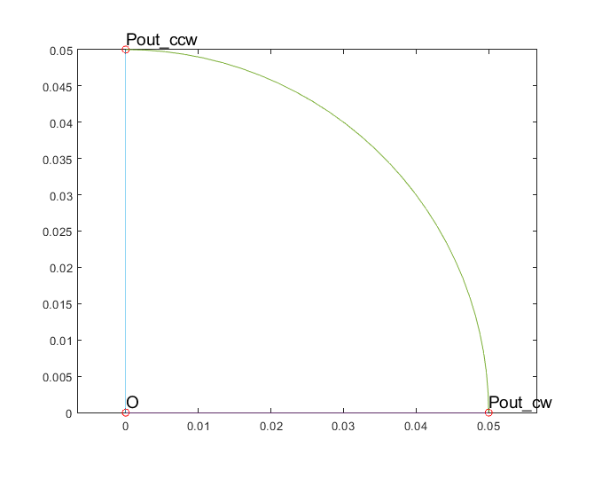
With this in mind, we create three Points:
%creating Points
O = Origin(lcar_center);
Pout_cw = Point([dim.Rout;0], lcar_ag);
Pout_ccw = Pout_cw.mirror(angle_pole);
The first point O is, unsurprisingly, the origin located at (0, 0). The next point Pout_cw then represents the outermost corner point of the minimal symmetry sector, on the intersection of the x-axis and the rotor circumference. The subscript cw refers to the fact that the Point lies on the clockwise boundary. Finally, we get the corresponding counter-clockwise boundary point P_ccw by mirroring Pout_cw across the pole pitch.
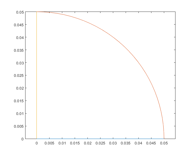
Next, we create the Surface for the rotor core. Next, we specify its outer boundary by adding to it (in the correct order) the
-
LinebetweenOandPout_cw -
ArcbetweenPout_cwandPout_ccw, centered atO. This Arc is named ‘n_ag’, to tellEMDtoolit lies on the airgap surface, to allow for automatic airgap mesh generation later on. -
Line between
Pout_ccwandO
and then add the newly-created surface to the rotor core Domain.
%creating surface
core_surface = Surface('');
core_surface.add_curve(geo.line, O, Pout_cw);
core_surface.add_curve(geo.arc, Pout_cw, O, Pout_ccw, 'n_ag');
core_surface.add_curve(geo.line, Pout_ccw, O);

%adding surface to domain
core_domain.add_surface(core_surface);
For clarity, the figure below shows the three points above, as well as the core surface.
Note:_ As you can read in the documentation, Arcs have to be strictly less than 180 degrees in span. Thus, the above example will fail for two-pole machines. For robustness, we should use an extra third point Pmid_ccw = Pout_cw.rotate(angle_pole/2); on the airgap surface, with corresponding two airgap Arcs.
Finally, we will have specify that the clockwise and counter-clockwise boundaries are periodic - to allow for correct mesh replication and finally correct boundary conditions in the final model.
%setting periodicity
geo.set_periodic(O, Pout_cw, O, Pout_ccw);
Hint: When making geometries, it often extremely useful to temporarily plot Points and Surfaces inside the .create_geometry method. Below is a snippet of how our example here could be debugged.
O.plot('O', 'ro');
Pout_cw.plot('Pout\_cw', 'ro');
Pout_ccw.plot('Pout\_ccw', 'ro');
core_surface.plot();
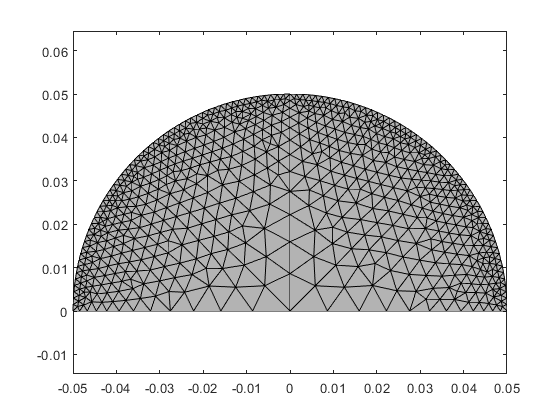
Using the example template
Finally, below is an example snippet of how the geometry template could be used, along with the resulting plots. As you can see, the elementary geometry only covers one pole pitch, while the final resulting mesh covers the symmetry sector of the final model-to-be (assumed 180 degrees here, to showcase the functionality).
dim = struct();

dim.p = 2;
dim.symmetry_sectors = 2;

dim.delta = 3e-3;
dim.Rout = 5e-2;

dim.rotor_core_material = 1;


figure(1); clf; hold on; box on; axis equal;
rotor = SimpleSolidRotor(dim);
rotor.plot_geometry();

rotor.mesh_geometry();
figure(2); clf; hold on; box on; axis equal;
rotor.visualize('linestyle', '-');
What’s the deal with Slots and Layouts
You may have already read of slot and layout templates of ´EMDtool´. In case you haven’t, the basic idea is to separate the creation of slot shape from the creation of the rest of the stator/rotor template, and also from the creation from the winding model. In other words, the goal is to be able to change the slot shape by simple supplying a different slot shape class without changing anything else, and to be able to change from say uniformly stranded winding to solid rectangular conductors without changing anything else.
While this is the recommended way of working and offers the highest flexibility for re-using code, it is understandable to sometimes want to quickly implement something simpler. Luckily, this is indeed possible.
You can, for instance, create a custom stator template, in which you also fully create the slot, and then populate it with conductors if that is your desire. This will (should) throw a warning about your template not being LayoutCompatible - this means that changing the .winding_model_type of your winding specification object will not automatically be reflected in the type of winding model created. Indeed, you should set this property to correspond to the type of winding you have created, meaning normally solid or stranded.