Example 1
Goal: Build and visualize a minimal radial-flux model using the Stator + VIPM1 templates.
Result: A valid geometry plot and a meshed RFmodel object ready for flux-density or torque analysis.
This script demonstrates setting up your very first EMDtool model. The general philosophy of EMDtool is based on templates - parametric geometry classes for stators and rotors (and sometimes frames, flux modulators, and other more exotic components) that can be mixed and matched as you like under a single model.
Granted, there are exceptions, like importing a DXF file, or manually creating an on-off geometry with no reusability in mind. But, those are indeed exceptions - the assumed workflow is based on maximal reusability.
This example is organized as follows. First, the dimensions are all stored inside a single Matlab structure. Next, a stator object and a rotor object are created. Finally, an object is created to represent a radial flux motor (or generator).
Let’s begin.
Setting some dimensions
General dimensions
We begin by creating an empty struct dim to hold all the dimensions.
Next, we define some general dimensions that will be used during various stages of the simulation process.
dim = struct();

dim.p = 3; %number of pole-pairs
dim.symmetry_sectors = dim.p*2; %number of model symmetry sectors
dim.delta = 1.5e-3; %airgap length
dim.leff = 150e-3; %stack length, or active length in general

dim.temperature_stator = 120; %stator temperature
dim.temperature_rotor = 120; %rotor temperature
Stator dimensions
Next, we will define some dimensions specifically for our would-be stator. We will be using the Stator template - a very general-purpose stator template. To know what dimensions are needed, you could check the online documentation, or type ‘help Stator’ in the Matlab command prompt.
We begin by defining some very high-level sizing variables. These are not needed, strictly speaking, but setting up your script like this can be handy if you wish to explore a large design space manually, while having most of the required changes handled automatically.
PHASES = 3;
SLOTS_PER_POLE_AND_PHASE = 2;
AIRGAP_FLUX_DENSITY_FOR_SIZING = 1;
First, we compute the number of slots:
dim.Qs = PHASES * 2*dim.p * SLOTS_PER_POLE_AND_PHASE;
Next, we will define a winding specification object. These are subclasses of the PolyphaseWindingSpec class, and take care of several important aspects:
- Defining the winding layout in engineering terms
- Defining the .xy and .dq methods for moving between the synchronous frame and instantaneous phase currents
- Specifying if the winding is modelled as infinitely stranded or as solid massive conductors
- Specifying the number, shape, type, etc of the conductors used
- Computing and returning several winding quantities of interest like the number of series-turns per phase
Since we want our machine to have a distributed winding scheme, we use the DistributedWindingSpec subclass. Finally, we assign the object to dim.stator_winding.
winding = DistributedWindingSpec(dim);
winding.N_layers = 1; %winding layers
winding.N_series = 12; %turns per single coil
winding.phases = PHASES; %phases
winding.a = dim.p*2; %parallel paths
dim.stator_winding = winding;
Next, we define the inner and outer radius of the stator. Again, we have included some hard-coded logic to handle different pole counts.
%inner and outer diameter
dim.Sin = 157e-3/2; %inner radius of stator
if dim.p == 1
    dim.Sout = dim.Sin / 0.5;
elseif dim.p == 2
    dim.Sout = dim.Sin / 0.6;
else
    %very rough
    dim.Sout = dim.Sin / 0.67;
end
Next, we begin defining some slot dimensions. Specifically, these are not seen by the Stator class itself. Instead, we could have specified a stator_slot dimension, to use a specific StatorSlotShape object. Since we have not specified any, the general-purpose Slot1 is used instead.
- The recommended approach of working with EMDtool is to use the Slot-Layout workflow. This allows dropping in different slot shapes to an existing parent geometry, and/or different conductor layouts into an existing slot geometry. While it can make things more complex to implement and understand, and even hinder analysing some edge cases, it tends to make 98 % of all analysis cases significantly easier.
%slot opening and bottom specs
dim.htt_taper_s = 1e-3; %slot opening, straight part before taper
dim.htt_s = 1.5e-3;
dim.wso_s = 2e-3;
dim.r_slotbottom_s = 1.2e-3;

%yoke height
hys = 2*pi*dim.Sin / (2*dim.p) * AIRGAP_FLUX_DENSITY_FOR_SIZING * 2/pi / 2 / 1.5;
dim.hslot_s = abs(dim.Sout - dim.Sin) - hys;
dim.wtooth_s = 2*pi*(dim.Sin + dim.htt_s)/dim.Qs * 0.6;
Next, we demonstrate an optional cooling hole feature of the Stator class.
%adding cooling holes to the yoke just because
dim.alpha_cooling_hole = 0.3;
dim.h_cooling_hole = 2e-3;
dim.h_cooling_rib = 4e-3;
A Note on Materials
Finally, we define some materials. Specifically, we use the SteelLibrary class to access the built-in Materials library of EMDtool.
- The SteelLibrary will return an object of the basic Material class. While this class is rather powerful and general purpose, special classes such as the HystereticMaterial and DemagMaterial1 do exist.
- Important: Most geometry templates create local copies of the materials given as inputs. In other words, none of the materials in stator.materials will be the same object as the one set into dim.stator_core_material. Importantly, changing the material properties of the here-created object after the stator object has been created will have no effect on the simulation results.
- For common questions on defining new materials, please see the documentation page.
%materials
dim.stator_core_material = SteelLibrary.create('M270-35A');
dim.stator_stacking_factor = 1;
dim.stator_wedge_material = 0;
Rotor dimensions
Next, we move onto the rotor dimensions. In some cases, there can be a naming overlap between two dimensions, in which case we could define a different dimensions script for the rotor. Here, as in 98 % of all cases, using the same script suffices.
We will be using the VIPM1 class, a simple but powerful template of a V-type IPM motor.
We first define the main dimensions
dim.Rout = dim.Sin - dim.delta; %outer radius
dim.Rin = 30e-3; %inner or shaft radius
followed by the magnet size and angle.
dim.w_mag = 30e-3; %magnet width
dim.h_mag = 6e-3; %magnet height
dim.angle_mag = pi/180 * 20; %V-opening angle in radians
Next, we define the desired thicknesses of the iron bridges:
dim.w_bridge_interpole = 5e-3; %thickness of the bridge between adjacent poles
dim.w_bridge_center = 2e-3; %bridge between magnets
dim.w_bridge_out = 1e-3; %outer bridge
and some sizes for the air-pockets:
dim.w_pocket_in = 2e-3;
dim.w_pocket_out = 1e-3;
Finally, we define the materials used. For the core, we use the same material as for the stator core. For the magnet material, we use the (linear) material created by the PMlibrary class.
dim.magnet_material = PMlibrary.create('N42SH');
dim.rotor_core_material = dim.stator_core_material;
dim.shaft_material = 1;
Creating geometries and a model
Now, we have all dimensions set, and we can set up some geometries and a model to use.
Geometries and visualization
We begin by creating the geometries - instances of the desired template classes, and then visualizing them.
stator = Stator(dim);
rotor = VIPM1(dim);

%plotting geometries
figure(1); clf; hold on; box on; axis equal;
stator.plot_geometry();
rotor.plot_geometry();
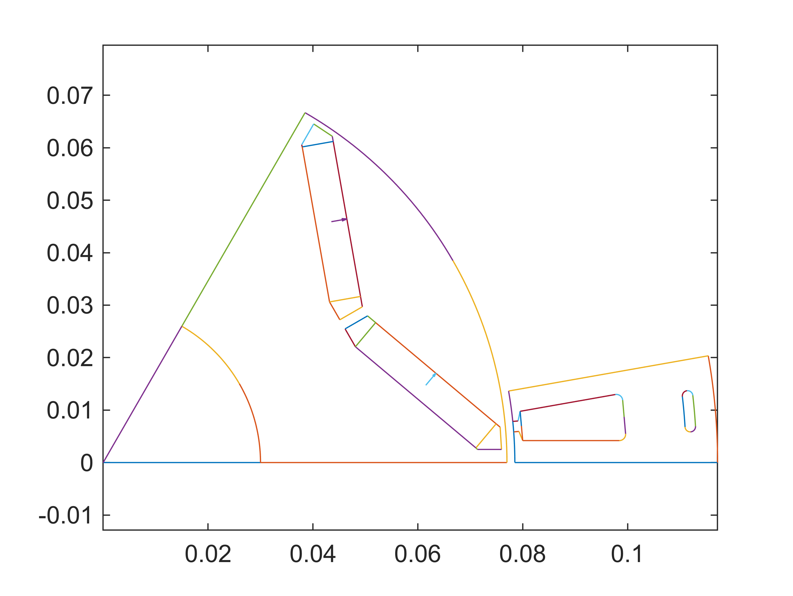
When defining the geometries for the first time, it is a good idea to temporarily end the script here, either by a breakpoint or a return statement. The human eye is a wonderful tool, and a designer with a bit of experience can often see if a geometry looks correct.
For automatic checking, we can call the built-in feasibility checks. These are not foolproof, but haven’t so far failed the author nonetheless:
assert(stator.check_feasibility(), 'Stator seems invalid.')
assert(rotor.check_feasibility(), 'Rotor seems invalid.')
Finally, a note on an important EMDtool feature: the geometry objects commonly only describe the minimal symmetric region, such as a slot or a pole-pitch. Special cases (such as less-symmetric distribution of stator cooling channels) may require the minimal region being larger - this is indeed possible in EMDtool but somewhat less common. Please contact support if this is of interest.
Model and visualization
Finally, we create an RFmodel object to represent our radial flux machine. This class, being a subclass of the MotorModelBase encapsulates a large amount of functionality required, including computing the torque produced and assembling a general simulation results summary.
motor = RFmodel(dim, stator, rotor);
gmsh path E:\Software\Work\gmsh-4.11.1\ loaded from preference group 'emdtool'
For now, we suffice ourselves with the visualization capabilities:
figure(2); clf; hold on; box on; axis equal;
motor.visualize('plot_axial', false, 'plot_ag', true, 'plot_nodes', true);
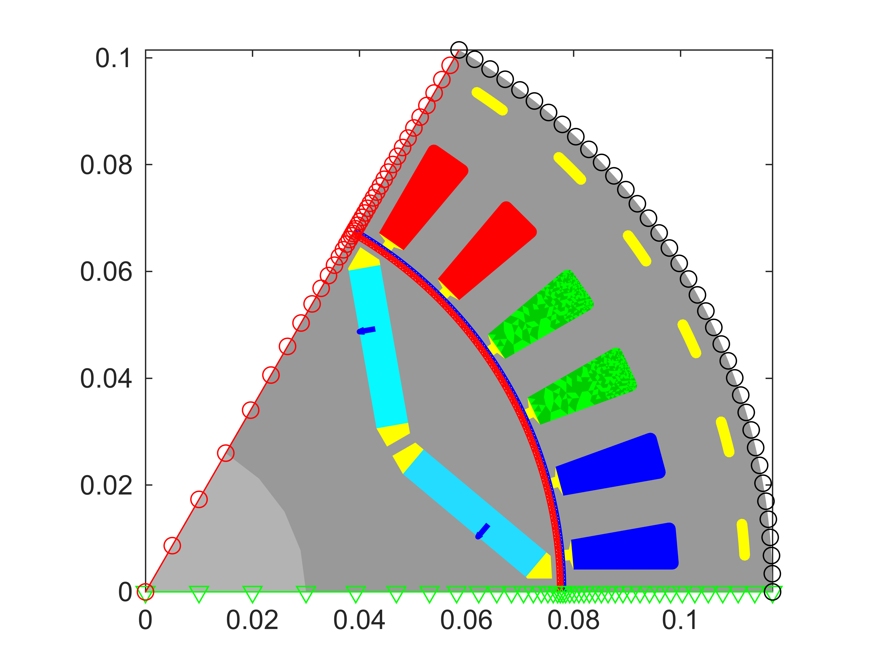
Please note that we normally wouldn’t plot the boundary nodes (periodic and Dirichlet/flux insulation) or the airgap mesh for any ‘finished’ model - however they are useful in the initial stage for verifying that everything works correctly. This is doubly useful for those implementing templates of your own.
Before concluding this example, below are some notes for those interested in the finer working of things:
- It is possible to mesh the geometry objects before initializing the model object, either by calling stator.mesh_geometry() or stator.mesh_elementary_geometry() and then stator.replicate_elementary_mesh()
- The associated mesh is then saved to stator.mesh. Boundary and edge data is also saved in similar fashion.
- When adding a geometry object to the model, the object is meshed if it already hasn’t. Importantly, some indices are updated - please see the MotorModelBase documentation.
Finally, let’s verify that the example ran correctly:
whos motor
  Name       Size            Bytes  Class      Attributes

  motor      1x1                 8  RFmodel