Example 1a
Goal: Manually build a geometry, to be later encapsulated in a geometry template.
Result: A valid geometry visualized and meshed.
This script demonstrates building a geometry from scratch, using a simple industrial-style straight-magnet IPM as an example.
The geometry is built inside a script rather than a function, to maintain access to all variables for easier debugging. At the same time, the code is organized in such a way that it could be reused inside a .create_geometry method of a new template, with minimal changes.
Please also see the second, template-creation tutorial found here.
Foundations
Dimensions
Aligned with the template philosophy, we first set up a structure of all the dimensions required. Normally, these would of course set up outside the template class-to-be, but keeping them in the same script here keeps things neat and tidy.
dim = struct();

%these follow general EMDtool naming
dim.p = 2; %number of pole-pairs
dim.symmetry_sectors = 2*dim.p;
dim.delta = 1e-3; %airgap

%these are not needed here per se, but
% allow dropping the finished geometry
% into an RFmodel for instance
dim.leff = 100e-3; %stack length
dim.temperature_rotor = 100;
dim.temperature_stator = 120;

dim.Rout = 0.05; %rotor outer radius
dim.h_mag = 10e-3; %magnet thickness
dim.w_mag = 55e-3; %magnet width

%thickness of bridge between air-pocket and OD
dim.w_bridge = 1e-3;

%shaft radius
dim.Rin = dim.Rout - dim.h_mag - 20e-3;

%materials
% See https://www.emdtool.com/documentation/knowledge_base/defining_materials.html
% for defining custom materials
dim.magnet_material = PMlibrary.create('N42');
dim.rotor_core_material = SteelLibrary.create('M270-35A');
dim.rotor_stacking_factor = 0.95;
Building Blocks
Here, we begin actually creating the geometry. As the very first step, we instantiate an empty SynRotorBase object, to have access to some usable methods.
this = SynRotorBase(); %we inherit some basic methods from the SynRotorBase
this.dimensions = dim;
An actual template would omit this step obviously.
Next, we set up three building blocks that recur in every template (with the possible exception of circuits).
Material Initialization
We add material objects to the geometry:
mcore = this.create_and_add_material(dim.rotor_core_material);
mmag = this.create_and_add_material(dim.magnet_material);
mair = this.create_and_add_material(0);
We use the .create_and_add_material utility method which achieves multiple goals at once:
- Avoids adding multiple copies of the same material (if e.g. shaft and core material turned out to be the same)
- Creates a material object from an integer, if some built-in common materials are used.
- Creates a new copy of an given material object. This is important from statelessness / statefulness point of view, as e.g.
mmag != dim.magnet_material. On the flip side, clear copies generally are needed; having a same material object for both the stator and rotor both would result in element indexing errors.Domain Initialization
We create Domains for representing all the important parts of the geometry, and add them to the object.
Core = LaminatedDomain('Rotor_core', dim.rotor_stacking_factor, mcore);
Magnet = Domain('Magnet', mmag);
Magnet.remanence_direction = pi/dim.p/2;

Air = Domain('Rotor_air_pocket', mair);

this.add_domain(Core, Magnet, Air);
Creating Circuits
This is not strictly needed, but in general we need some Circuits - an EMDtool term for anything carrying a current density, be it windings or induced macroscale eddy currents.
Let’s add a circuit for the magnets. We also include a check for the conductivity, to avoid simulation errors from an infinite resistivity.
if mmag.electrical_conductivity > 0
    MagnetCircuit = ExtrudedBlockCircuit('Magnet_eddies');
    MagnetCircuit.block_height = dim.leff / 4; %4 axial segments
    MagnetCircuit.add_conductor(SolidConductor(Magnet));
    this.add_circuit(MagnetCircuit);
end
Geometry Creation
Next, we begin creating the actual geometry.
As a summary, EMDtool geometries are defined with a few steps
Pointobjects represent pointsCurves(LinesandArcs) join points- A set of Curves defines a
Surface - A Surface (or multiple) are assigned to a Domain
There are some utility methods for all, such as mirroring and translations. In general these all return a copy of the original object. If this is undesired, most methods have an _inplace version of the same method, acting on the original object.
Curves are created automatically when calling the surface.add_curve method. However, we can also create them manually if needed. Both are demonstrated in the example.
Importantly, dublicates should be avoided:
- Points at identical coordinates
- Curves defined by identical points
- Surfaces defined by identical curves
Duplicate points should be handled at the meshing stage, and are sometimes unavoidable (e.g. when using Surface copying methods).
Furthermore, there aren’t any automatic validity checks for the geometry, so care should be taken that
- Curves do not cross. If they do, a new Point should be defined for the crossing point, and the Curves split accordingly.
- Surfaces don’t overlap.
Utility Numbers
First, we calculate some utility numbers. We set the characteristic lengths - target mesh edge lengths in any given part of the geometry. Furthermore, we calculate the pitch of the pole in radians.
%determining characteristic lengths = mesh density near a Point
lcar_ag = Airgap.characteristic_length(this);
lcar_mag = dim.h_mag/3;
lcar_core = pi*dim.Rin/dim.p / 5;

apole = pi/dim.p; %angle of single pole
Actual Geometry
First, we create a surface for the magnet. We will have the magnet oriented along the x-axis in the beginning, and then rotate it for the standard the EMDtool orientation.
O = Origin(); %Point at Origin

%create a magnet surface, centered around y=0 for now
% Solve point x with the Pythagoran theorem
x_out = sqrt( (dim.Rout - dim.w_bridge)^2 - (dim.w_mag/2)^2);

%clockwise points
P_mag_out_cw = Point([x_out; -dim.w_mag/2], lcar_ag);
P_mag_in_cw = Point([x_out-dim.h_mag; -dim.w_mag/2], lcar_mag);

%counterclockwise points by mirroring around the y=0 axis
P_mag_out_ccw = P_mag_out_cw.mirror(0);
P_mag_in_ccw = P_mag_in_cw.mirror(0);

%creating magnet surface
smag = Surface('');

%magnet lines
smag.add_curve(geo.line, P_mag_out_cw, P_mag_out_ccw);
smag.add_curve(geo.line, P_mag_out_ccw, P_mag_in_ccw);
smag.add_curve(geo.line, P_mag_in_ccw, P_mag_in_cw);
smag.add_curve(geo.line, P_mag_in_cw, P_mag_out_cw);
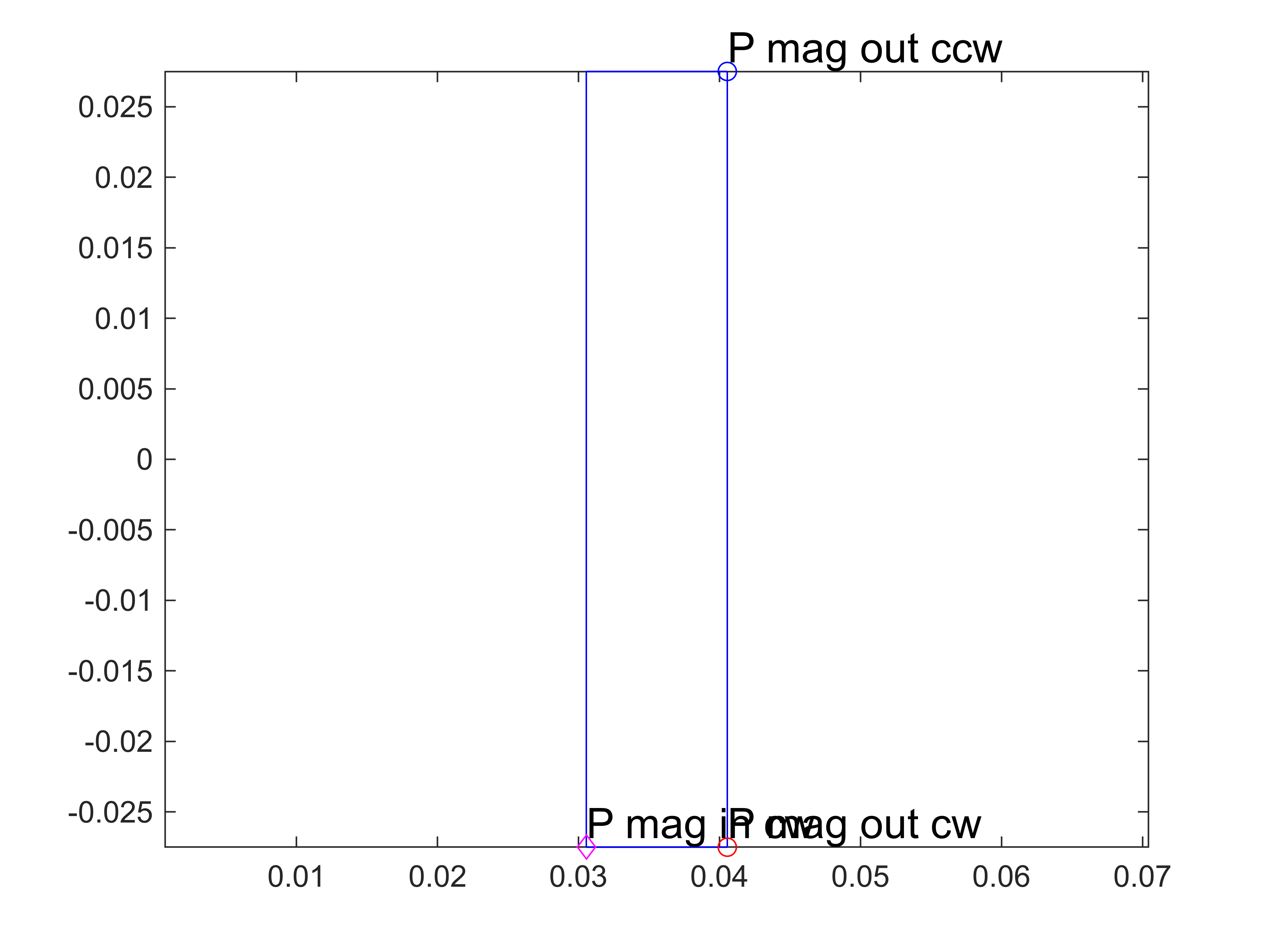
At this point, we visualize the magnet to make certain all is as we expect. Obviously, these visualization lines would be omitted in an actual template.
%visualizing magnet and some points
figure(1); clf; hold on; box on; axis equal;
smag.plot('b');
P_mag_out_cw.plot('P mag out cw', 'ro');
P_mag_out_ccw.plot('P mag out ccw', 'bo');
P_mag_in_cw.plot('P mag in cw', 'md');
Next, we rotate the magnet to the correct orientation and check.
%rotating so that the clockwise periodic boundary lies on y=0 axis
% inplace rotation = we are not creating a copy like smag.rotate would do
smag.rotate_inplace(apole/2);

%plotting again
figure(2); clf; hold on; box on; axis equal;
smag.plot('b');
Next, we create a surface for the iron core.
%creating points for the core
P_ag_cw = Point([dim.Rout; 0], lcar_ag);
P_in_cw = Point([dim.Rin; 0], lcar_core);

%corresponding points the counter-clockwise boundary
P_ag_ccw = P_ag_cw.mirror(apole);
P_in_ccw = P_in_cw.mirror(apole);

%one mid-points so that the geometry works for 2-pole machines, too, as
%arcs must be less than 180 degress
P_ag_mid = P_ag_cw.rotate(apole/2);
P_in_mid = P_in_cw.rotate(apole/2);

% initial core surface
score = Surface('');

%airgap facing curves
score.add_curve(geo.arc, P_ag_cw, O, P_ag_mid, 'n_ag');
score.add_curve(geo.arc, P_ag_mid, O, P_ag_ccw, 'n_ag');

% other curves
score.add_curve(geo.line, P_ag_ccw, P_in_ccw); %counterclockwise boundary

%inner / flux insulation / dirichlet boundary; must be named 'n_dir'
score.add_curve(geo.arc, P_in_ccw, O, P_in_mid, 'n_dir');

%let's create the second curve manually
core_id_arc_2 = Arc(P_in_mid, O, P_in_cw);
score.add_curve(core_id_arc_2);

%clockwise boundary
score.add_curve(geo.line, P_in_cw, P_ag_cw);
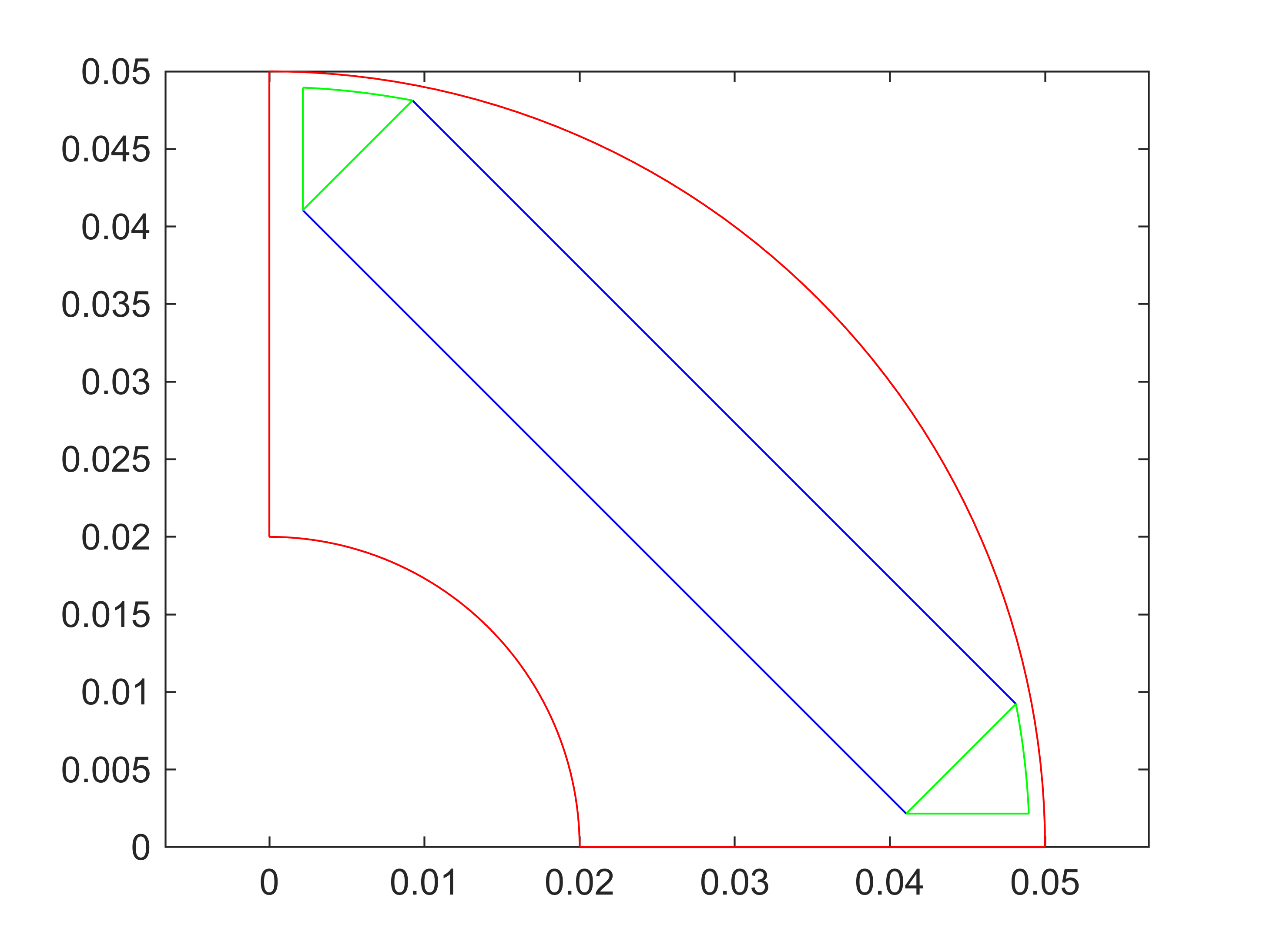
Again, we plot the core.
%plotting core
score.plot('r');
Next, we tell EMDtool that the magnet is inside the core, called a hole. Note that the magnet must be fully inside the core. If it breaks the outer surface, it is not a hole but a separate surface, in which case the core surface must be redefined accordingly.
%adding magnet as a hole
score.add_hole(smag);
Finally, we create some air pockets at the short edges of the magnet. These consist of two straight line segments (one being the short edge of the magnet), and an Arc leaving the desired thickness of iron between the air pocket and the rotor OD.
%creating air pockets, semitriangular
P_pocket_cw = P_mag_out_cw.copy();
P_pocket_cw.y = P_mag_in_cw.y;

%solving x to have an Arc for the outer curve of the air pocket, with
%dim.w_bridge worth of iron left between it and the airgap surface
P_pocket_cw.x = sqrt((dim.Rout - dim.w_bridge)^2 - P_pocket_cw.y^2);
P_pocket_ccw = P_pocket_cw.mirror(apole);

%clockwise pocket
spocket_cw = Surface('');
spocket_cw.add_curve(geo.line, P_mag_in_cw, P_mag_out_cw);
spocket_cw.add_curve(geo.arc, P_mag_out_cw, O, P_pocket_cw);
spocket_cw.add_curve(geo.line, P_pocket_cw, P_mag_in_cw);
spocket_cw.plot('g');

%counterclockwise pocket
spocket_ccw = Surface('');
spocket_ccw.add_curve(geo.line, P_mag_in_ccw, P_mag_out_ccw);
spocket_ccw.add_curve(geo.arc, P_mag_out_ccw, O, P_pocket_ccw);
spocket_ccw.add_curve(geo.line, P_pocket_ccw, P_mag_in_ccw);
spocket_ccw.plot('g');
%add pockets as holes
score.add_hole(spocket_cw, spocket_ccw);
Finally, we finalize the geometry, by adding the Surfaces to the corresponding Domains.
%add Surfaces to corresponding domains
Core.add_surface(score);
Magnet.add_surface(smag);
Air.add_surface(spocket_cw, spocket_ccw);
Finally, we make sure that the boundary conditions have been defined properly
%set periodic boundary
geo.set_periodic(P_in_cw, P_ag_cw, P_in_ccw, P_ag_ccw);

%we tell the seconc ID arc to be flux insulation:
core_id_arc_2.name = 'n_dir';

%finally, we verify (just to show it) that the first ID arc has been
%properly assigned into a Dirichlet boundary.
% The Arc.from_points first searches for an existing Arc defined by those
% points, the extra boolean argument 'false' tells it to throw an error if
% no such arc is found
core_id_arc_1 = Arc.from_points(P_in_ccw, O, P_in_mid, false);
assert(core_id_arc_1.name == "n_dir");
Geometry is ready
This is where we would return from a template’s .create_geometry method. We check the feasibility of the geometry - this method checks for overlapping Curves and Surfaces. Not foolproof and misses T-intersections, but a nice additional step, still.
rotor = this;
rotor.check_feasibility(); %should return 1 or true
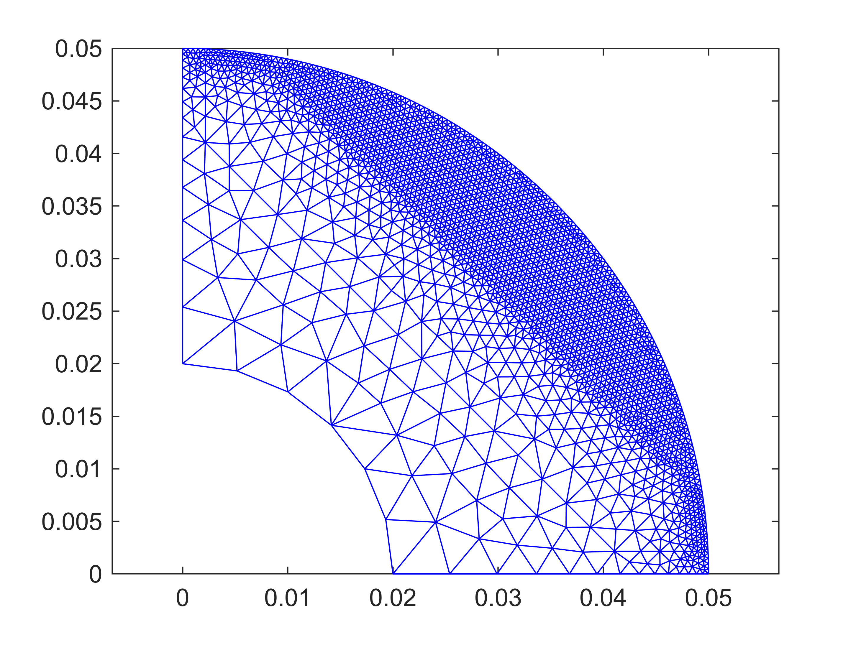
Finally, we manually mesh the geometry and visualize both the mesh and the geometry.
%meshing
rotor.mesh_geometry();
gmsh path E:\Software\Work\gmsh-4.11.1\ loaded from preference group 'emdtool'
%visualizing mesh, check that we don't have overlapping elements or
%anything
figure(4); clf; hold on; box on; axis equal;
rotor.mesh.triplot([]); %all elements = []
%visualizing rotor in general
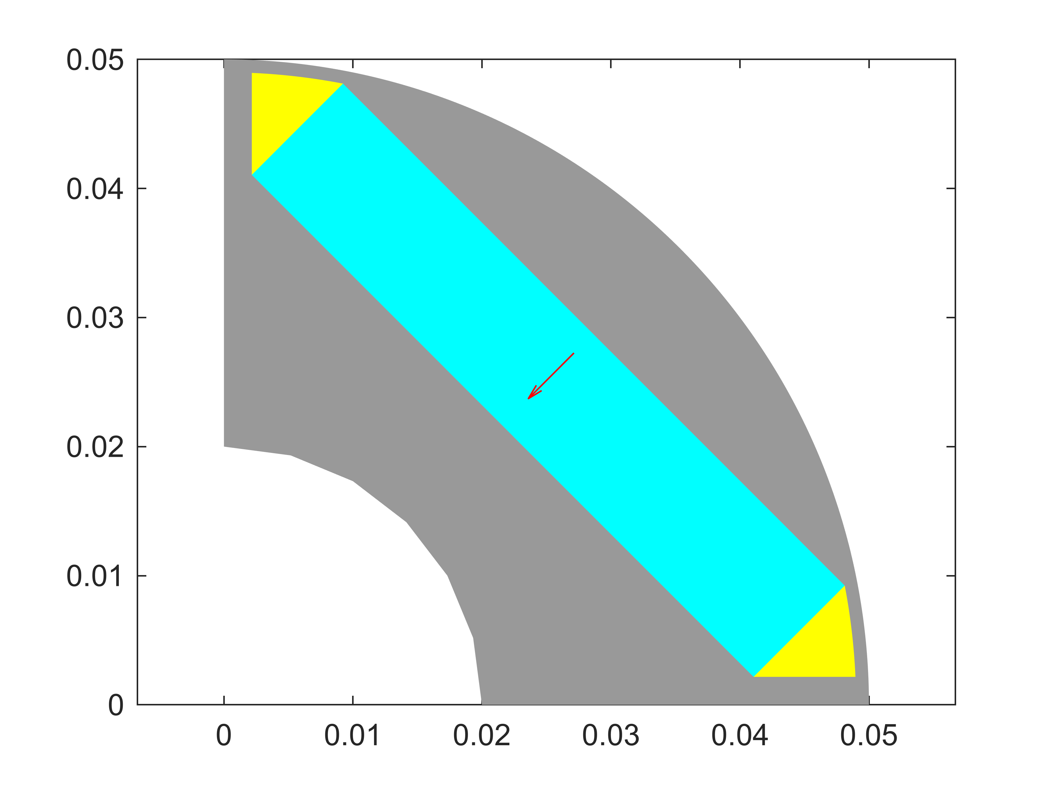
figure(5); clf; hold on; box on; axis equal;
rotor.visualize();